Adding Measurement Points
How to Execute
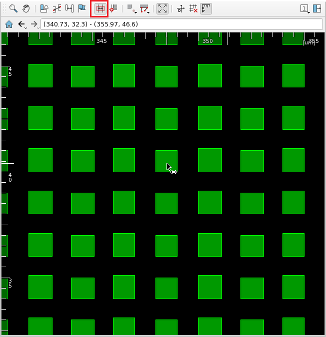
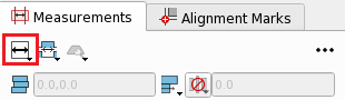
Run Directly on Screen
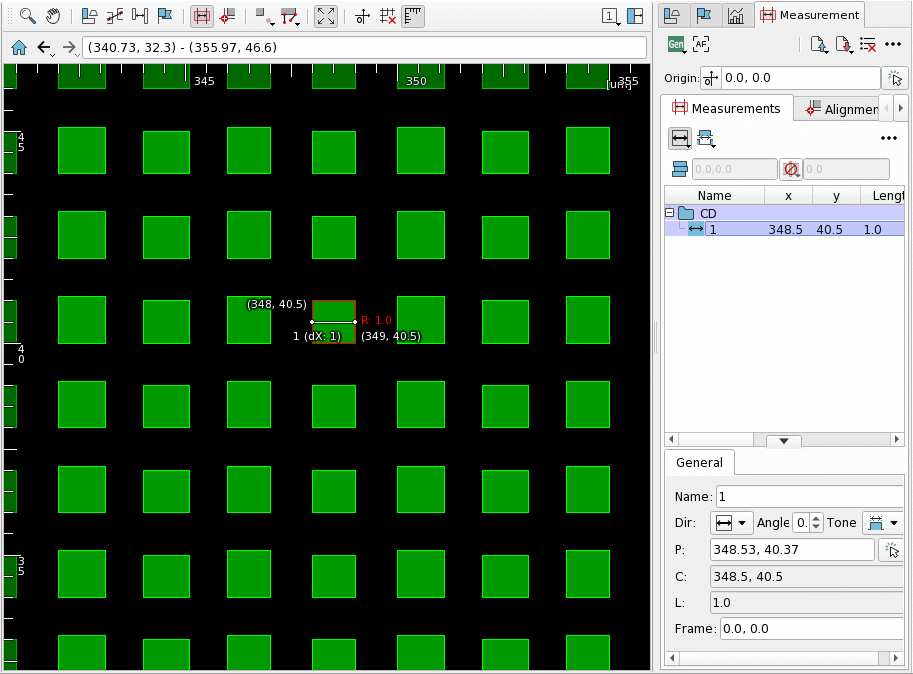
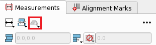
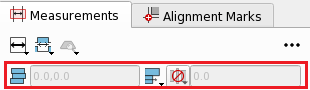
Switch to Add Measurement mode, select the direction, type, etc. of the measurement point in the Measurements tab toolbar of Measurement Panel, then left-click on screen.
The measurement points are saved to Measurement Panel and displayed on screen.
Right-click on the displayed measurement point to open the context menu, containing the following items in addition to the default context menu items.
| Menu | Action |
|---|---|
| Duplicate | Duplicate the selected measurement point. Refer to Duplicating Measurement Points page. |
| Create LS Detect Condition | Create a LS Detect condition from the selected measurement point. Refer to Extract and Execute Conditions from Measurement Points in LS Detect page. |
| LS Detect with Item | Execute LS Detect with the condition of LS Detect created from the selected measurement point. Refer to Extract and Execute Conditions from Measurement Points in LS Detect page. |
| Pattern Match with Item | Execute Pattern Match using the selected measurement point and the figure existing at the position. Refer to Pattern Match page. |
| Group | Group the selected measurement points. Refer to Grouping Measurement Points page. |
| Shift | Move the selected measurement point. Refer to Moving Measurement Points page. |
| Jump | Center the screen on the measurement point. |
| Start Auto Navigation | Start the auto-navigation from the specified measurement point. Refer to Auto Navigation Bar page. |
| Select/Deselect | Toggle selection of the measurement point on screen. |
| Show | Show/hide the measurement point on screen. |
| Display/Name | Show/hide the name of the measurement point on screen. |
| Display/Coordinates | Show/hide the coordinates of the measurement point on screen. |
| Display/Length | Show/hide the line length of the measurement point on screen. |
| Display/X/Y Components | Show/hide the length of the measurement point in both X and Y directions on screen. |
| Display/Angle | Show/hide the angle of the measurement point on screen. |
| Color | Change the display color of the measurement point on screen. |
| Properties | Show the properties of selected measurement point. |
| Delete | Delete the selected measurement point. |
Direction and Type of Measurement Point
The direction and type of the measurement point can be specified from Direction on the Measurements tab toolbar.
| Icon | Item | Action |
|---|---|---|
| 0 degree | Create a 0 degree measurement point. | |
| 45 degree | Create a 45 degree measurement point. | |
| 90 degree | Create a 90 degree measurement point. | |
| 135 degree | Create a 135 degree measurement point. | |
| Box | Create measurement points in two directions, 0 and 90 degrees. | |
| Any Angle | Create a measurement point of any angle. Specify the angle in the Angle for Measurement dialog which opens when it is selected. | |
| Horizontal Hole | Create a 0 degree measurement point at Dot/Hole. | |
| Vertical Hole | Create a 90 degree measurement point at Dot/Hole. | |
| Box Hole | Create a measurement point measuring both 0 and 90 degrees at Dot/Hole. | |
| Edge-Edge | Create a measurement point from line end to line end. You need to specify two points. | |
| Auto Angle | Create a measurement point with direction perpendicular to the edge nearest to the point. | |
| View | Create a measurement point to check the figure at the selected point. | |
| Corner Round | Create a measurement point at a corner. | |
| Point-Point | Create a measurement point between any two points. You need to specify two points. | |
| Auto Hole Short | Create a measurement point on the short edge of Dot/Hole boundary box. | |
| Auto Hole Long | Create a measurement point on the long edge of Dot/Hole boundary box. | |
| Line Space Point-Point | Create measurement points in lines and spaces between any two points. You need to specify two points. | |
| Area | Create a measurement point to measure an area of figure on specified point. | |
| Area by 2 Points | Create measurements point to measure areas of figures in specified area. Created measurement points are grouped. You need to specify two points. |
Tone of the Measurement Point
The tone of the measurement point is specified from Tone on the Measurements tab toolbar.
| Icon | Item | Action |
|---|---|---|
| Auto | Create a measurement point at the selected point. | |
| Line | Create a measurement point on the figure. | |
| Space | Create a measurement point in space. | |
| Pitch Up-Up | Create a measurement point from the start of one figure to the start of the next. | |
| Pitch Down-Down | Create a measurement point from the start of one space to the start of the next. | |
| Target CD Width | Create a measurement point on a figure with the specified length. Specify the Target CD and the tolerance in the Target CD dialog which opens when it is selected. | |
| Target CD Space | Create a measurement point in space with the specified length. Specify the Target CD and the tolerance in the Target CD dialog which opens when it is selected. | |
| Target CD Pitch Up-Up | Create a measurement point from the start of one figure to the start of the next with the specified length. Specify the Target CD and the tolerance in the Target CD dialog which opens when it is selected. | |
| Target CD Pitch Down-Down | Create a measurement point from the start of one space to the start of the next with the specified length. Specify the Target CD and the tolerance in the Target CD dialog which opens when it is selected. |
Search Width
Search Width can be switched from Search Width on the Measurements tab toolbar.
| Icon | Item | Action |
|---|---|---|
| No Search | Add a normal measurement point. | |
| Min | Add a measurement point at the minimum width around the specified coordinates. | |
| Max | Add a measurement point at the maximum width around the specified coordinates. |
Other Settings of Measurement Points
With Jog
Creates a measurement point on a figure that contains jogs.
| Icon | Item | Action |
|---|---|---|
| With Jog | Specify whether to tolerate jogs. You can specify two tolerances in um units. |
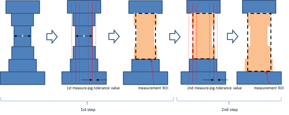
When With Jog is specified, the jog on the figure is smoothed, and the measurement point is created for the smoothed figure. The target of smoothing are edges that is within the range specified by With Jog, based on the line length of the measurement point. The smoothing is performed up to two times. The first one is done using the first tolerance value and the original measurement length. The second one uses the second tolerance value and the weighted average value of the measurement length from the first smoothing. The second smoothing is skipped if the tolerance value is 0.
Jog Type
When With Jog is specified together, the measurement point is created based on the smoothed figure and the actual figure.
| Icon | Item | Action | Result |
|---|---|---|---|
| Average | Create a measurement point for the smoothed figure. | 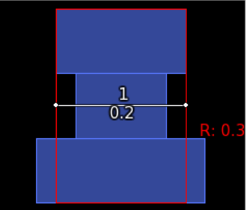 |
|
| Min | Create a measurement point using the smallest length of the actual figure which is the source of the smoothed figure as measurement line. | 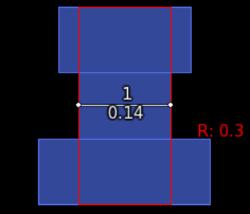 |
|
| Max | Create a measurement point using the largest length of the actual figure which is the source of the smoothed figure as measurement line. | 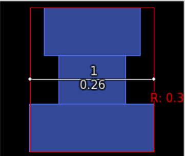 |
Assist Size
Ignore assist line or space when creating a measurement point.
| Icon | Item | Action |
|---|---|---|
| Off | Create a measurement point without ignoring any figures. | |
| Assist Line | Create a measurement point ignoring small figures. Can only be created inside space. | |
| Assist Space | Create a measurement point ignoring small spaces. Can only be created inside figure. |
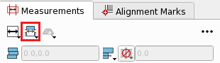
Run from the Create Measurement Point Dialog
Right-click the blank area of the datalist in Measurements tab of Measurement Panel to open the Create Measurement Point dialog.
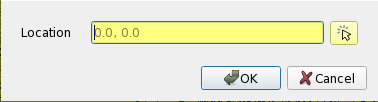
Enter the coordinates and press OK to add the measurement point.
Run with Measure Points File
Click the  icon on Measurement Panel and select
 Load Measure Points File to open the Load Measure Points dialog.

Select a Measure Points File and press OK to append measurement points described in the file to the datalist.
Refer to Measure Points File page.
Output Measurement Points to a File.
The measurement points in the datalist can be saved to a text file.
Click the  icon on Measurement Panel and select
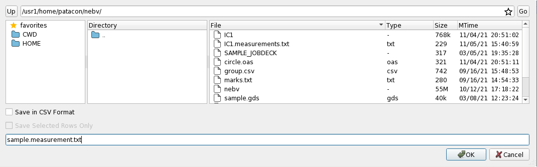
 Save as Measure Points File to open Save Measure Points as dialog.
| Item | Action |
|---|---|
| Save in CSV format | Save the Measure Points File in CSV format. |
| Save Selected Rows Only | Save only the selected measurement points in Measurement Panel. |
Specify the output file name and press OK to save. The output has the following format:
# Measure Points File Created by libebv at DATE nebv VERSION
Out-Origin OUT-ORIGIN 0, 0
# Alignment mark
# Measurement points
1 CD X 125.804, 162.637
2 CD Y 107.876, 158.599
# End of File
Run from the Command Line
Specify --measure-file option with a Measure Points File to add alignment marks after startup.
You can also specify the filename to save measurement points (including alignment marks) using --measure-file-out option.
By specifying as follows, measurement points and alignment marks will be created for figure_file, and the results will be output to measure_points.txt.
$ nebv --measure-file=/path/to/measure_point_file.txt --measure-file-out=/path/to/measure_points.txt /path/to/figure_file
Refer to Measure Points File page.
See --measure-file, --measure-file-out in Boot Options page.
Similarly, you can specify the filename to save CD Results File using --cd-file option.
$ nebv --measure-file=/path/to/measure_point_file.txt --cd-file=/path/to/cd_results_file.txt /path/to/figure_file
See --cd-file in Boot Options page.
Related Settings
You can change the display method of the measurement point from the Preference. See preference Action/Recipe Creation/Add Measurement page for detail.